
Flow Rate Vs Pressure Drop FE Series Check Valves
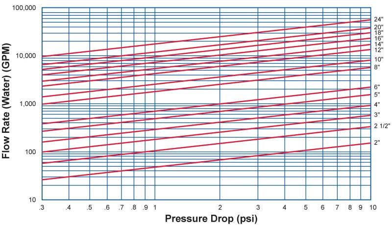
Flow Rate Vs. Pressure Drop – FE Series Check Valves
ASME Class 150 to ASME Class 2500
Notes:
• The above chart is for theoretical calculations ONLY. Please contact our office with your exact specifications and you will be provided with factory calculations.
• The Curves shown above relate to valves provided with standard rated springs.
• Stronger springs may be required to ensure faster reaction if very large changes in velocity occur.
• We will provide valves to match your performance requirements.
• It should be borne in mind that a media (liquid) velocity in the pipeline of 10 ft per second is considered to be desirable for normal applications.
Installation Data
The Sure Flow Check valve is designed so that it is centralized between the flanges when the stud bolts are in position. The outside diameter of the body is equal to the bolt circle PCD minus the diameter of one bolt.
It is suitable for use in a variety of orientations. In horizontal lines the valve is installed with the pins vertical (i.e. with the pin retainers at the top). For sizes 6” and upwards the valve is tapped to take an eyebolt for lifting.
Arrows cast into the body indicate the normal direction of flow.
Before initial installation it is advisable to open the plates by hand since, if the valve is held in store for a period of time, the corrosion inhibitor may have caused the plates to stick to the body and line pressure may not be sufficient to break this seal.
If the bottom half of the studs are installed first they will serve as a platform to support the valve while the gaskets and other studs are inserted. Similarly, if the valve is to be removed from the line, the top half of the studs should be removed and the bottom half slackened.

For a full page, printable version of this information, please click on the PDF icon.